

Written by Samir Baydoun | Plant Maintenance
Many exhaust liner failures are blamed on age. In reality, premature failures are often traced back to design decisions made years earlier. When liners are installed in high-temperature, high-velocity exhaust systems, seemingly small details can dramatically affect service life.
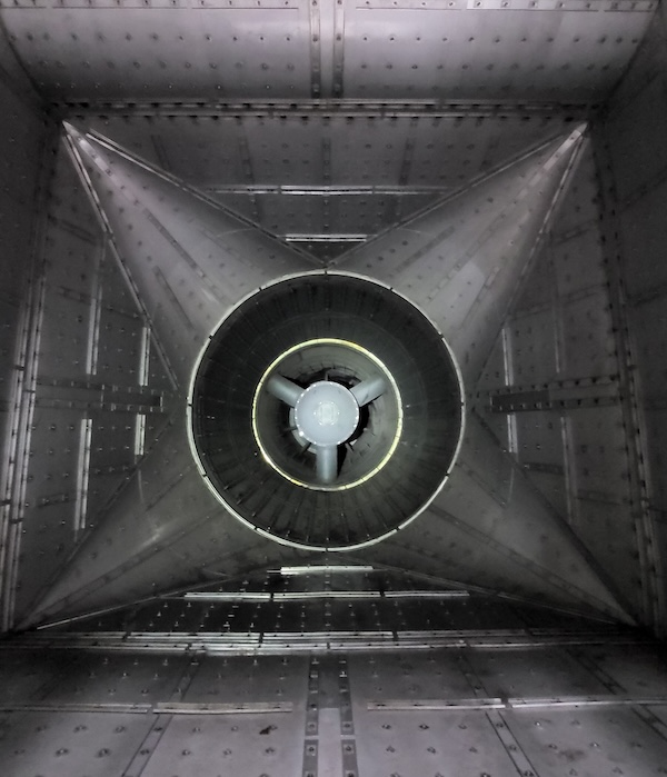
High-turbulence regions such as diffusers, plenums, and burner duct sections place unique demands on liner systems. If those demands are not properly accounted for during design, the result can be liner buckling, stud failures, cracking, and costly unplanned outages.
Understanding the design factors that contribute to these failures can help plant operators make better decisions during inspections, repairs, and replacement projects.
Understanding Flow Conditions in Exhaust Systems
Not all areas of an exhaust system experience the same flow characteristics. Regions closer to the turbine discharge typically experience highly turbulent flow, while areas farther downstream tend to see more stable flow conditions. The difference matters because turbulence creates constantly changing pressure and vibration loads on the liner system.
Diffusers and plenums deserve special attention because flow in these areas may approach the liner from multiple directions. Unlike relatively predictable flow paths, turbulent zones can generate swirling forces that add additional stress to mounting hardware and liner sheets.
Computational Fluid Dynamics (CFD) allows engineers to evaluate exhaust flow patterns and identify areas where turbulence creates additional loading on the liner system. This information can then be used to optimize liner sheet thickness, stud spacing, stiffening details, and other design features for the expected operating conditions.
Why Liner Sheets Must Lap with the Flow
One design detail that is frequently overlooked is the direction in which liner sheets are lapped.
When liner sheets are installed so that their overlaps face with the direction of flow, exhaust gases pass smoothly across the sheet surfaces. However, when sheets are lapped against the flow, the leading edge can become a point of attack for high-velocity gases.
As flow catches the exposed edge, it can cause vibration, lifting, and localized deformation. Over time, this movement may lead to buckling of the liner sheet itself. More importantly, the exhaust flow can begin to work beneath the liner sheet, increasing stress on the mounting system.
The additional movement transfers cyclic loading into the studs, which accelerates fatigue and increases the likelihood of studs cracking or separating.
Stud Spacing and Load Distribution
Mounting studs are one of the most critical structural elements in an exhaust liner system. Their purpose is to secure the floating liner while allowing for thermal expansion and contraction.
In high-turbulence regions, stud spacing becomes especially important. Excessive spacing forces individual studs to carry larger loads and absorb greater vibration forces.
Some liner systems have been built with stud spacing as wide as 18 to 24 inches. While this approach may reduce material and fabrication costs, it can significantly increase stress concentrations and shorten fatigue life.
In higher-turbulence areas, closer stud spacing will distribute loads more evenly across the liner system. Proper spacing allows the load to be shared among multiple attachment points, which reduces the stress on any single stud and improves overall durability.
Edge Stiffening and Batten Channels
Turbulence can also cause liner sheets to vibrate and deflect. Without adequate stiffening, repeated movement can eventually lead to distortion, fatigue cracking, and premature failure. Batten channels are commonly used to stiffen liner sheet edges and improve structural stability. In low-turbulence applications, stiffening may be required only at selected edges.
High-turbulence zones are different. Because flow can approach from multiple directions, engineers often need to provide full perimeter stiffening to prevent excessive movement. This is particularly important in diffuser sections, plenums, and burner duct applications where the vibration levels are often highest. Proper edge stiffening helps maintain liner position and reduces damage related to fatigue over the life of the system.
Material and Thickness Considerations
The materials used in an exhaust liner can have a major impact on how long the system lasts.
It may be tempting to use thinner liner sheets to reduce costs, but that decision can create problems down the road. Thinner materials are generally more prone to buckling, warping, and vibration-related damage, especially in high-turbulence areas. While some manufacturers use 14-gauge or even thinner material, many high-temperature applications benefit from heavier 10- or 11-gauge sheets that are better able to withstand the stresses of daily operation.
Temperature is another important factor. Applications that perform well at one temperature may not hold up at higher temperatures. For example, Type 409 or Type 304 stainless steel may be suitable for applications operating around 1,250°F. However, as exhaust temperatures climb into the 1,300°F to 1,800°F range, higher-grade materials such as Type 309 stainless steel are often needed to maintain strength and resist heat-related deterioration.
Selecting the appropriate material for the operating environment is essential to achieving long service life.
Designing for Long-Term Performance
When exhaust liners fail prematurely, the root cause is often found in the original design rather than simple age.
The performance of an exhaust liner system is affected by various design details, including flow orientation, stud spacing, liner gauge, edge stiffening methods, weld quality, and material selection. While it may seem natural to focus on minimizing initial project costs, overlooking these elements may increase the likelihood of fatigue-related failures and shorten the lifespan of components.
Plant operators who understand how the design elements affect the system performance can make more well-informed decisions during inspections, repairs, and replacement projects. This proactive method helps mitigate risk, maximize service life, and increase overall system reliability.
Planning a repair or replacement project? Let SVI BREMCO help you identify potential design issues before they lead to costly downtime and premature liner failures.