

Written by Tucker York | Power Plants
SVI BREMCO was asked to assist a combined-cycle power plant with a complex engineering problem: the removal of a Heat Recovery Steam Generator (HRSG) transition duct turning vane weldment positioned immediately downstream of a 120 MW class gas turbine while maintaining adequate flow distribution into the first stage HP tube module. Throughout the service life of the HRSG unit, the customer expressed ongoing maintenance issues with the “egg-crate” style turning vane set, having had to modify the support structure and individual vanes over several years to reduce aerodynamic loading conditions and corresponding structural or weld failures. These alternations compromised the effectiveness of the turning vane set, and SVI BREMCO was asked to remove the weldment in favor of an alternate flow modifier, such as a perforated distribution plate or flow deflector (kick-panel) positioned in the aft half of the transition duct.
To properly evaluate this application, SVI BREMCO initiated a Computational Fluid Dynamics (CFD) analysis to evaluate the flow distribution in the HRSG exhaust system at the customer’s combined-cycle location. The study focused on assessing the aerodynamic performance of the existing turning vane set and exploring alternative flow conditioning strategies to improve exhaust flow dispersion while addressing structural fatigue concerns, routine maintenance cycles, and acceptable system thermal efficiencies.
The Importance Of Flow Distribution On HRSG Performance
An HRSG is a critical component in combined-cycle power plants, extracting thermal energy from high-temperature exhaust gases and converting it into steam for additional power generation. Flow distribution directly impacts HRSG operational efficiencies and the longevity of HP, IP, and LP boiler equipment. Uneven flow distribution can lead to localized hot spots, inefficient heat transfer, and increased thermal stresses on tube bundles. This can result in premature failure of critical components, higher maintenance costs, and reduced overall plant efficiency.
Proper flow conditioning into the HP stage of the HRSG ensures
- Uniform Heat Transfer: Optimized heat exchange across tube bundles, improving steam generation efficiency.
- Reduced Thermal Fatigue: Eliminating or minimizing high-velocity zones prevents localized overheating, reducing stress-induced failures in tubes and structural elements.
- Lower Pressure Drop: Optimized flow conditioning minimizes flow resistance, reducing the power required for exhaust movement and improving overall combined-cycle performance.
- Extended Component Life: Balanced aerodynamic performance helps maintain the integrity of the HRSG unit by preventing material erosion and dynamic fatigue-related issues.
Using the CFD Modeling Approach
SVI BREMCO developed the HRSG exhaust CFD model using Siemens STAR-CCM+ application software, incorporating Reynolds-Averaged Navier-Stokes (RANS) equations with the Shear Stress Transport (SST) k-ω turbulence model. To reduce the complexity and focus of the modeling effort, the exhaust system CFD model extended from the gas turbine diffuser, through the turning vane set, into the downstream HRSG inlet transition duct and ended in the first HP tube bundle region.
Key assumptions included steady-state flow, isothermal conditions (neglecting heat transfer through insulated, lined ducting), and gravity effects. The various HRSG HP, IP, and LP boiler tube bundles were modeled as 3D porous regions, a standard industry practice where it is computationally difficult to model all tube/fin geometries. An appropriate empirical porous resistance coefficient represents pressure drop across each tube bundle stage. Also, the thermal duty for each tube bundle is modeled using convective heat transfer sinks. SVI Dynamics assumed a 15° inlet swirl profile for the gas turbine exhaust, inducing a cyclonic flow behavior into the downstream gas path (turning vane set, transition duct, flow modifiers, HP tube bundle stage, etc.).
CFD Simulation Cases And Resulting Flow Behavior
The CFD study iterated through multiple configurations to reach an optimized solution for the customer, considering baseline flow distribution as the OEM “egg-crate” turbine vane concept. Illustration 1.4.1 shows the OEM geometry from the turbine diffuser to the HRSG HP tube bundle stage. To understand flow distribution variation from case to case, SVI BREMCO evaluated clipped face velocities at the HP stage within ± 15% of the average face velocity, resulting in a percentage of area covered. In the case of the baseline configuration (with turning vane set), 33.54% of the HP stage face area is within this established bandwidth (VX, AVG. = 27.8 ft/s ± 15%).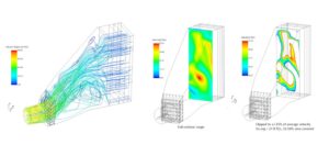
Illustration 1.4.1: OEM Design, Resulting Flow Distribution.Case variations examining the removal of OEM turning vanes, various deflector plate (kick-plate) designs, and perforated diffuser screen geometries were conducted to understand design sensitivities, including perforation pattern open area percentages, perforation hole diameters, and deflector plate or diffuser screen heights.
The following examination shows the flow dispersion performance with the OEM turning vane set removed, a worst-case performance illustration. In this case, 17.95% of the HP stage face area is within the established comparison bandwidth (VX, AVG. = 27.7 ft/s ± 15%).

Through subsequent cases, SVI BREMCO determined optimal deflector plate heights, perforation patterns, and top edge conditions to propel exhaust flow toward the upper regions of the HRSG HP tube bundle stage. The following illustration shows an intermittent iteration of the deflector plate design with a 36-inch tall profile, 4-inch diameter holes, 15.7% open area, and serrated top edge to produce improved mixing downstream of the deflector. In this case, 29.9% of the HP stage face area is within the established comparison bandwidth (VX, AVG. = 27.7 ft/s ± 15%).

Through the iterative modeling process, SVI BREMCO determined the optimal deflector plate height was 48 in. tall, allowing the customer to fabricate, install, and maintain the weldment while not compromising worker safety when traversing the deflector plate during planned outages. The ideal solution maintains a deflector plate height of 48 inches, with 6-inch diameter holes, 37% open area, and a serrated top edge to improve mixing along the boundary layer and change potential downstream large-scale flow structures. In this case, 30.8% of the HP stage face area is within the established comparison bandwidth (VX, AVG. = 27.7 ft/s ± 15%). Illustration 1.4.4 shows the final design recommended by SVI BREMCO.

SVI BREMCO CFD Model Key Findings and Recommendations
- Turning Vanes vs. No Vanes: The baseline OEM configuration with complete turning vane weldment downstream of the gas turbine diffuser duct demonstrated 33.5% of the cross-sectional area within ±15% of average velocity. The complete removal of vanes significantly degraded flow distribution to 17.9%, leading to high-velocity gradients and excessive turbulence in the inlet transition duct. Although typical HRSG installations recommend the distribution efficiency be as high as 70%-80%, the original OEM concept sets a credible baseline target.
- Deflector Plate Optimization: Multiple trials by SVI BREMCO showed a 36-48 inch tall solid deflector plate improved velocity uniformity but introduced a recirculation zone immediately downstream of the plate. Adding perforations and serrations along the top edge of the plate enhanced distribution while reducing wake turbulence.
- Partial Distribution Grid Performance: Optimal flow dispersion at the HSRG HP stage was created using a 114 in. tall perforated grid, yielding 45.7% cross-sectional uniformity and showing effectiveness in flow homogenization while minimizing pressure losses. However, this concept was not implemented due to aerodynamic loading concerns, installation complexities, and worker safety issues when transversing the weldment during outage periods.
- Recommended Implementation: SVI BREMCO suggested the 48” tall deflector plate to the customer as a final, acceptable technical solution. With a 37.03% perforation open area (4” dia. holes) and 30.8% velocity uniformity, the solution offers a balance of performance and manufacturability. Its axial load distribution profile further enhanced long-term structural stability compared to conventional turning vanes.
Does Your Plant Need Help Maintaining HRSG Thermal Efficiency?
Optimizing thermal efficiency in HRSG units is essential for maintaining plant performance, reducing maintenance costs, and extending equipment lifespan. Through advanced CFD modeling and iterative design analysis, SVI BREMCO delivered an innovative deflector plate solution that improves flow uniformity while addressing structural integrity and maintenance concerns. Additionally, as a turnkey industrial power plant services provider, we also engineered, fabricated, and installed the system. If your plant is facing challenges with HRSG flow distribution, SVI BREMCO’s expertise in engineering-driven solutions can help. Contact us today to explore how our customized flow modifiers can enhance your plant’s efficiency and reliability.