

Written by Will Medlock | Power Plants
Addressing the critical challenges of aerodynamic design can save costs, improve efficiency, extend system life, and enhance acoustic and thermal performance.
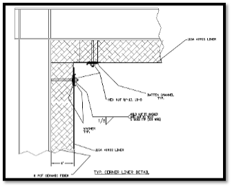
With exhaust gas temperatures ranging from 800F to 1250F+ and local velocities as high as 300 ft/s, it is safe to say combustion turbine exhausts are a chaotic and violent environment. Generally, simple cycle combustion turbine exhaust systems are simple rectangular, round, or combination ducts with few internal components. Duct walls are typically constructed using a painted carbon steel shell and an internally insulative liner system designed to reduce heat transfer to the exterior duct wall. The cross section of a duct wall liner system typically includes, from inside to outside, an 11- or 12-gauge, stainless steel liner sheet and a layered arrangement of ceramic fiber insulation, all held together by stainless steel studs welded directly to the interior of the duct wall.
The most common major interior component of a simple cycle combustion turbine exhaust system is the silencer. The silencer is generally referred to as “baffles” arranged in the gas flow path by an acoustic engineer to optimally attenuate the acoustic energy of the system to manageable levels for plant personnel as well as site neighbors. Exhaust silencers are constructed as welded stainless-steel assemblies with acoustic infill specifically for the extreme temperature and turbulent environment of the downstream side of a natural gas combustion turbine.
Unfortunately, original exhaust systems are often designed with commercial terms top of mind, instead of system durability and longevity. These original systems are often undersized, made with inadequate materials thickness, selection, and fabrication, arranged with abrupt turns, or a combination of these issues.
These design flaws and the resulting system maintenance issues down the road shine a light on the importance of aerodynamic design considerations in original and retrofit simple cycle combustion turbine exhaust system designs.
Aerodynamic design considerations begin with the goal of reducing the turbulence of the exhaust gas flow after it exits the turbine and makes its way through the exhaust system. Optimized aerodynamics can provide the following benefits to the exhaust and the system overall:
Reduced flow-induced damage to exhaust components
When aerodynamics is not considered properly in exhaust design, a myriad of structural integrity issues can arise.
- Extreme velocities can prematurely deteriorate the internal liner system and acoustic panels.
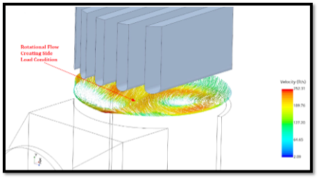
- Rotational flow can create side-loading conditions on the exhaust silencer
In retrofit projects, aerodynamics can often be improved to promote long term durability after the retrofit is complete.
Improved acoustic performance
Exhaust system aerodynamics significantly impact the overall acoustic performance of the system. Poor aerodynamics can result in flow-induced self-noise creation even with an exhaust silencer in place. Additionally, there are circumstances where poor aerodynamic design sends a disproportionate amount of exhaust flow through certain silencer gap passages which greatly hinders the silencer performance.
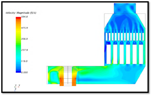
With aerodynamic improvements in mind during a retrofit project design, the flow distribution can be made significantly more even, providing improved acoustic performance of the silencer as well as improved structural durability due to reduced local flow velocity maximums.
An emerging solution that addresses both aerodynamic and structural challenges is the BAR silencer—a proprietary technology developed to improve flow uniformity and silencer durability. Unlike traditional parallel baffle silencers, which can lock flow into narrow channels, BAR silencers feature a matrix of perforated bars that allow for the three-dimensional dispersion of exhaust gas. This design not only reduces side loading and self-generated noise but also improves low-frequency attenuation and pressure distribution, enhancing both acoustic performance and system longevity in high-temperature, high-velocity environments.
Optimal pressure drop across the exhaust system
This important overall system design consideration is heavily dependent on the aerodynamic design of the exhaust. Design considerations such as the size of the cross-sectional flow area, length of flow development, smoothness of transitions, strategic placement of silencing components, and silencer design are vital in the design of an efficient exhaust system. In some extreme cases, pressure drop can be improved by over 1” w.c. across the entire exhaust system with retrofits that are significantly less obstructive to the turbine exhaust flow.
Temperature management
Proper aerodynamic design reduces extreme localized velocities in the system which can lead to concentrated hot spots. We know from simple convective heat transfer physics that the rate of heat transfer increases with the increase in velocity of fluids. With optimal aerodynamics, the gas flow will be as laminar as possible with minimized flow velocity, which helps to reduce the deterioration of the internal liner system and transfer of damaging heat to the exterior duct walls.
These confounding factors highlight the importance of aerodynamic considerations in the design of original and retrofit combustion turbine exhaust projects.